Recently Scattered Spider (G1015) have been gathering attention from a range of attacks against UK retail, namely attacks against Marks and Spencer, Harrods and Co-Op. These have led to extensive service disruption, with some firms being able to limit the impacts caused more than others. This is in addition to a range of attacks in previous years against telecommunication and Business Process Outsourcing (BPO) providers. Given the impact felt by the recent attacks against retail firms, understandably other businesses want to assess their defences against such attacks.
Threat Intelligence
To start, let’s summarise the TTPs of Scattered Spider from public threat intelligence sources, along with some ideas on how these can be tested safely. I will focus heavily on the initial stages of a Scattered-Spider attack, as this is the typical focus for most companies, though reviewing the post-exploitation TTPs would also be advisable!
The report also lists Bring-Your-Own Vulnerable Driver (BYOVD) as a TTP, which could be considered for testing, or ensuring that BYOVD-specific controls are enabled, such as the corresponding ASR rule in MDE.
Google/Mandiant
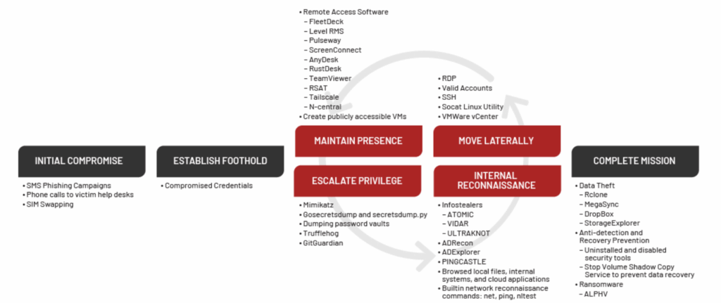
A recent Mandiant report lists a range of TTPs which mirror the above, with a handy diagram (below) which shows a graphical mapping of the TTPs across the attack chain.
Notably there are a lot of other lower-skilled TTPs listed here, such as using Mimikatz and secretsdump.py, which should be readily detected by any EDR.
Following a successful vish or phish of a user, Scattered Spider were observed to then perform more detailed OSINT into the targets, looking to identify potential answers to their security questions or perform targeted SIM swapping attacks.
From the above threat intelligence, it is clear to see several common approaches taken by Scattered Spider, specifically around vishing and the widespread use of social engineering tactics. To assess this, there are several different attacks which can be simulated through either a red or purple team exercise.
Vishing
The main TTP used by Scattered Spider appears to be the use of vishing to gain access to their targets. As part of this, the following could be tested:
Vishing the IT Support helpdesk to gain a password and/or MFA reset
This should include both a ‘standard’ and ‘privileged’ user as targets
Assess controls in place on video calling and internal messaging applications
Can an external Teams user directly message/call employees?
Are external tenants only to communicate internally following approval?
Can the SOC correlate the activity from an IT Helpdesk call to any malicious behaviour (I.e. MFA Methods added or unusual account activity)
Perform vishing attacks directly against high-profile or privileged users
Currently this is not listed by any public TI sources, but would be a logical next step for Scattered Spider TTPs
This would have to be carefully planned with considered guardrails and limitations to prevent causing harm or distress to any users.
Performing internal vishing (E.g. social engineering a user from the position of another internal user) can be challenging during a purple team exercise, due to the lack of technical controls which can be implemented to prevent otherwise legitimate behaviour. Instead, this can be somewhat simulated by attempting some of the ‘Risky Sign In’ behaviour below. For example, by simulating the theft of valid credentials, and attempting to authenticate as a secondary account. This would simulate the stages before an internal vishing attack, as the attacker gains access to the internal environment.
Another approach could be to simulate a supply chain compromise, from the position of a IT provider/supplier being compromised. By configuring a separate (trusted) tenant, and then creating an account within it to simulate a third party user or contractor. This could be a privileged account, or simply a ‘standard’ account, which is within a tenant that has a level of trust into the main tenant. Several tests could then be performed from the trusted into the trusting tenant:
Performing vishing and phishing attacks
Such as sharing a link to a credential capture portal, sending various payloads via email or Teams
Throughout these TTPs, the behaviour of email and web filtering and gateway solutions should be checked for any discrepancies compared to the same behaviour performed from an ‘untrusted’ account.
Credential re-use onto SSO-enabled platforms such as Citrix, AVDs or other internal systems
Enumeration of shared cloud resources or internal data repositories
Credential Capture
Scattered Spider appear to make extensive use of credential capture sites, such as those created by Evilginx. These sites are often hosted using domains which mimic the brand being targeted, which could act as another point of detection. Some potential tests include:
Phishing using a credential capture lure
Sending credential capture payloads from a domain impersonating the target (e.g. auth-TARGET_NAME.com)
Assessing that alerts are raised following credential capture activity
Registering domains which impersonate the target to test brand protection controls and/or typo-squatting detections
This can also blur into testing ‘risky sign-in’ activity, such as performing signins from non-compliant hosts or those in unusual geographies. This can be performed by:
Using VPS’s in unusual geographies to simulate a foreign login
Testing ‘impossible travel’
Authenticating using an abnormal host or browser/user agent (E.g. Kali Linux, Firefox)
Authenticating following an MFA Fatigue attack (See later!)
Performing a secondary authentication whilst the user is legitimately signed in.
Credential Re-Use
Credential stuffing or re-use attacks appear to also be used by Scattered Spider, along with a number of other threat actors. Whilst this is a commonly used technique, there are several password spraying TTPs which are worth assessing:
Evaluate breached credentials and combolists for leaked credentials
Depending on the scope and appetite of the customer, performing more targeted OSINT into high profile or privileged users to identify passwords used on personal accounts could be performed – subject to approval!
Perform targeted password spraying using any leaked credentials, including potential modifications (E.g. London101! -> London102!)
Widespread password spraying using passwords relating to the company or industry
With access to a valid account, a wider range of tests can be simulated as an assumed compromise-style test to assess the post-authentication controls:
Attempt to add phone/SMS based MFA methods to an account
If they are, then perform MFA Fatigue tests against it.
Sign in using a non-compliant device
Attempt to perform typical early kill chain behaviour
Searching SharePoint/internal resources for passwords or internal data
Gathering of Teams and Outlook data
Add new MFA methods to the account
Change the password of the account
Follow the ‘Risky Sign In’ activity above
Evaluation of the current password policy and banned password phrases
Remote Management and Monitoring (RMM)
Attempting to download and install various RMM tools on a corporate device should be sufficient to raise alerts, especially if the executable is not being installed via an approved method (E.g. InTune). CISA has a specific advisory on this, which contains additional information.
Attempt to run various commands through a provided console (If it has one) or through cmd/powershell.
Alerts could be raised at all points of these tests, though this can be challenging due to the executables potentially being allowed by policy, for example of AnyConnect is a corporate solution for screensharing or client communications. It would also be a good exercise to ensure any actions performed via a RMM can be successfully attributed to a RMM session by the SOC/IR teams, rather than a more generic attribution to activity via a CLI.
Additional Considerations
Whilst the TI mentioned above lists a range of TTPs, it is also important to consider some of the emerging initial access tradecraft seen by other threat actors, such as Device Code phishing, ClickFix and Living Off Trusted Sites (LOTS). Whilst I dont believe this has been publicly observed as being used by Scattered Spider yet, given the success of such techniques it would be advised to ensure these are also tested, as the TTPs in use may evolve!
A lot of this post focuses on technical controls and testing, but this activity also has a number of potential table top scenarios which could be produced from it to ensure the correct processes are in place. For example:
How would a third-party compromise be handled in light of the recent breaches?
What would the process be for handling AiTM alerts being raised against a privileged IT account?
What would the response be if a mass password-spraying attack was observed from known Scattered Spider infrastructure?
Specific training or guidance for staff may be sensible given the uptick in active attacks from Scattered Spider recently. Training could focus on:
How to identify potential social engineering approaches, focusing on vishing specifically
How can users report suspicious internal messages or video calls
Raising awareness of current attacker trends, such as ClickFix
Recommendations
The FS-ISAC report and the Mandiant report have a range of recommendations on specific controls to be implemented, and would be a good starting point for any assurance activity.
Strap in for a thrilling ride of legal terms and jargon! Legal stuff is certainly not the reason most red teamers perform assessments, but it is a vital part of the role. I’ve wanted to learn more about the actual legal requirements behind we do certain things such as Rules of Engagement, so hopefully this will save some of the pain for others who are interested.
As with anything legal – this post is not official guidance and always do your own research!
Computer Misuse Act (CMA)
The Computer Misuse Act 1990, or CMA, covers a range of legal areas, and is closely related to the Data Protection Act (DPA), which concerns the usage and protection of data. In this post I will try and summarise what the CMA is, what it covers and the potential impacts.
The CMA doesn’t define what a computer is, due to the potential for this to rapidly change. Therefore it is considered as a device which can ‘store, process or retrieve information’.
A ‘Computer System’ is any “device or a group of interconnected or related devices, one or more of which, pursuant to a program, performs automatic processing of data”. ‘Computer Data’ is any “representation of facts, information or concepts in a form suitable for processing in a computer system, including a program suitable to cause a computer system to perform a function.”
The DPA defines personal data as any information relating to an identified or identifiable living individual.
Jurisdiction
Under section 4 of the CMA, liability for offences under sections 1, 3 or 3ZA requires proof of at least one ‘significant link’ with the ‘home country’ concerned (i.e. England and Wales). Notably this isn’t impacted if:
The accused isn’t in the home country at the time of the offence
The target of the CMA offence (e.g. the compromise host) isn’t in the home country
The technological activity which has facilitated the offending may have passed through a server based in the home country
Therefore, if someone commits a crime under Sections 1, 3 or 3ZA whilst in a foreign country, they may still be liable for prosecution within the UK if they are a UK national or their activity would be illegal in their current country.
As defined in section 5, in relation to an offence under Section 3ZA, any of the following rules would consist a ‘significant link’ with domestic jurisdiction:
That the accused was in the home country concerned at the time when s/he committed the unauthorised act (or caused it to be done);
That the unauthorised act was done in relation to a computer in the home country concerned;
That the unauthorised act caused, or created a significant risk of, serious damage of a material kind (within the meaning of that section) in the home country concerned.
As defined in section 6, even the act of conspiring to commit a crime under the CMA would be treated under the same ‘extended extra-territorial jurisdiction arrangements’. For example, you can be outside the UK whilst conspiring to commit a crime according to the CMA and still be liable for it within the UK.
Thresholds For Prosecution
The offence occurs when an individual causes a computer, which would include his own computer, to perform a function with intent to secure access.
This excludes simply having physical contact with a computer and the scrutiny of data without any interaction with a computer. Therefore the act of reading sensitive or confidential output or forms of eavesdropping are not crimes in themselves within the CMA.
The access to the program or data which the accused intends to secure must be ‘unauthorised’ access. For example:
There must be knowledge that the intended access was unauthorised; and
There must have been an intention to secure access to any program or data held in a computer.
The word ‘any’ indicates that the intent does not relate to the computer which the accused is at that time operating. Section 1(2) explains that the intent of the accused does not need to be directed at any particular program or data, mean that an attacker who accesses a computer without any clear idea of what they will find there would still be liable.
This can mean that a lot of the specific detail is pushed to individual policies when considering any testing or internal issues, such as acceptable use policies. Whilst these have no legal bearing, they would be a key consideration in cyber security testing. Cases such as DPP v Bignell [1998] 1 Cr App R8 highlight this, where police officers were found not guilty after requesting details for an indivudal which they didnt have permission to do so, but they did have legitimate access to the PNC.
Offenses
For cyber security professionals, the offenses highlight why effective approval processes are so important for testing, with all the offenses relying on the offender gaining unauthorised access to a system, and knowing that said access is not approved.
Section 1: Unauthorised access to computer material
The maximum penalty for this offense is 2 years imprisonment, making it the most ‘basic’ offense within the CMA. This relates to unauthorised access to a computer, where the access is unauthorised and the offender would know that at the time of the offense occurring.
Section 2: Unauthorised access with intent to commit or facilitate commission of further offences
The maximum penalty for this offense is 5 years imprisonment. This is somewhat of an extension to Section 1, due to the ‘further offenses’ detail. An example could be obtaining access with a view to transferring money.
This further offence can be conducted at a separate time, it just requires the link between the two offenses. This second offense may not be technically feasible – but if it is attempted then they could be liable for a Section 2 offense.
Section 3: Unauthorised Acts with intent to impair, or with recklessness as to impairing the operation of a computer
The maximum sentence for this offense is 10 years’ imprisonment. This covers acts such as DDoS or deliberate damage. Importantly, deliberate modification of data is not necessarily covered by this, unless it impacts the reliability or availability of the data.
The specific acts covered are covered in Section 3(2), either by directly causing or enabling the following impacts:
‘Impair’ the operation of a computer
Prevent or hinder access to any program or data on the computer
Impair the operation of any program or its data
This doesn’t have to be a permanent impact, it can be a temporary impact (Section 3(5))
Section 41(2) of the Serious Crime Act 2015 inserted section 3ZA, with effect from 3 May 2015.
This covers the causation, or ‘significant’ risk of causing ‘material’ damage. This again can be deliberately or ‘recklessly’ caused.
The maximum sentence is 14 years, unless the offence caused or created a significant risk of serious damage to human welfare or national security, as defined in Section 3 (a) and (b), in which case a person guilty of the offence is liable to imprisonment for life.
This is intended to cover the most serious cases concerning Critical National Infrastructure (CNI), with a large number of damages covered by this section. Damage is referred to as being ‘material’ if it leads to any of the following (Sections 3ZA(2,3)):
Damage to human welfare in any place, specifically:
Loss to human life;
Human illness or injury;
Disruption of a supply of money, food, water, energy or fuel;
Disruption of a system of communication;
Disruption of facilities for transport; or
Disruption of services relating to health.
Damage to the environment of any place;
Damage to the economy of any country; or
Damage to the national security of any country.
Section 3A: Making, supplying or obtaining articles for use in offence under Section 1, 3 or 3ZA
The maximum sentence for this is two years’ imprisonment. The rationale behind the creation of this offence is the market in electronic malware or ‘hacker tools’; which can be used for breaking into, or compromising, computer systems. For this, an ‘article’ is any program or data held in electronic form. This is the section likely most relevant to red teamers, given the large number of people involved in the open-source community. Whilst it is unlikely that Section 3A offences would be charged against someone contributing to open-source projects, it it worth considering!
This covers a wide range of activity relating to committing an offence under Sections 1, 3 or 3ZA:
Someone making, adapting, suppling or offering to supply any ‘article’
This also includes obtaining an ‘article’ in order to supply or use it
This is based on some of the following criteria/guidance:
Has the article been developed primarily, deliberately and for the sole purpose of committing a CMA offence (i.e. unauthorised access to computer material)?
Is the article available on a wide scale commercial basis and sold through legitimate channels?
Is the article widely used for legitimate purposes?
Does it have a substantial installation base?
What was the context in which the article was used to commit the offence compared with its original intended purpose?
Public Interest
The Crown Prosecution Service (CPS) has a great summary of the consideration for public interest in any case being raised:
As always, the public interest in a case features heavily. For example, where there is sufficient evidence to meet the evidential test under the ‘Code for Crown Prosecutors’, the following Public Interest factors should be carefully considered:
The financial, reputational, or commercial damage caused to the victim(s);
The offence was committed with the main purpose of financial gain;
The level of sophistication used, particularly sophistication used to conceal or disguise identity (including masquerading as another identity to divert suspicion);
The victim of the offence was vulnerable and has been put in considerable fear or suffered personal attack, damage or disturbance;
The mental health, maturity and chronological age of the defendant at the time of the offence.
Data Protection Act
The Act came into force on 25 May 2018. The Act updates data protection laws in the UK, supplementing the General Data Protection Regulation (EU) 2016/679 (GDPR), implementing the EU Law Enforcement Directive (LED), and extending data protection laws to areas which are not covered by the GDPR or the LED
The Act does not write the GDPR into UK law. The GDPR has direct effect in EU member states from 25 May 2018, which means the GDPR is already part of UK law. After the UK leaves the EU, the GDPR will be converted into UK law (with some amendments) under the European Union (Withdrawal) Act 2018.
Part 1 – Definitions
Several key terms are used within the DPA:
Term
Meaning
Personal Data
Any information relating to an identified or identifiable living individual. This definition does not include the extra detail in the GDPR which goes on to define an ‘identifiable living individual’
Identifiable Living Individual
A living individual who can be identified, directly or indirectly, in particular by reference to an identifier such as a name, an identification number, location data or an online identifier; or one or more factors specific to the physical, physiological, genetic, mental, economic, cultural or social identity of the individual.
Processing
In relation to information, means an operation or set of operations which is performed on information, or on sets of information, such as: collection, recording, organisation, structuring or storage; adaptation or alteration; retrieval, consultation or use; disclosure by transmission, dissemination or otherwise making available; alignment or combination; or restriction, erasure or destruction.
Data Subject
The identified or identifiable living individual to whom personal data relates.
Controller and Processor
Part 1 does not provide a single definition of controller and processor. Instead it points to the relevant Chapter or Part of the Act for the specific definition of these terms. As a general rule the definitions of controller and processor mirror those of the GDPR: ‘controller’ means the natural or legal person who alone or jointly with others determines the purpose and means of the processing of personal data; and ‘processor’ means the natural or legal person who processes personal data on behalf of the controller.
Filing System
Any structured set of personal data which is accessible according to specific criteria, whether held by automated means or manually and whether centralised, decentralised or dispersed on a functional or geographical basis
The applied GDPR
The GDPR as applied by Part 2 Chapter 3. In practice this means that the Act extends GDPR standards to: processing outside the scope of EU law or processing outside the scope of the GDPR other than processing covered by Part 3 (LED processing) or Part 4 (IS processing)
LED (Law Enforcement Directive)
Used where data is processed by competent authorities for law enforcement purposes
Part 2 – Data Processing
Part 2 of the DPA sets out how data processing can occur, and is heavily linked to the implementation and support of GDPR. Whilst GDPR was automatically enacted due to EU membership at the time, it provides the provision for member states to tailor the language to suit local laws and government. Some examples of this are DPA Part 2 Section 8 which more precisely implements GDPR Article 6 (1)(e), detailing the specific government and public bodies which can process data.
Special Categories
Schedule 1 details the various conditions which permit processing of special categories of personal and criminal offence data:
Part 1 – Conditions relating to employment, health and research
For an employer to process data under this part, any controllers must have an appropriate policy document in place
For public health bodies to process data, it must be conducted under the responsibility of a health professional or other person who has a duty of confidentiality under enactment or law.
For research purposes, it must have a public interest and be in accordance with Article 89(1) GDPR (as supplemented by s19 of the Act)
Part 2 – Substantial public interest conditions
This includes a wide range of potential topics, but all must follow the same underlying principles of being limited and only what is necessary.
Part 3 – Additional conditions relating to criminal offence data
Part 4 – Appropriate policy document and additional safeguards
Should such data be processed, several further policy documents must be created, which must:
Explain how the controller complies with the data protection principles set out in Article 5 of the GDPR;
Explain the controller’s policies for the retention and erasure of personal data processed under the relevant condition; and
Be retained, reviewed and (if appropriate) updated by the controller and (if requested) made available to the Information Commissioner, until six months after the controller ceases carrying out the processing.
Where appropriate policy documentation is required, the controller’s records of processing activities (under Article 30 of the GDPR) must include:
Details of the relevant condition relied on;
How processing satisfies Article 6 of the GDPR (lawfulness of processing); and
Details of whether the personal data is retained and erased in accordance with the appropriate policy documentation (and if not the reasons why not).
Data Transfer
From the GDPR regulations:
The GDPR imposes a general prohibition on the transfer of personal data outside the EU, unless:
Article 45 – the transfer is based on an adequacy decision;
Article 46 – the transfer is subject to appropriate safeguards;
Article 47 – the transfer is governed by Binding Corporate Rules; or
Article 49 – the transfer is in accordance with specific exceptions. One of the specific exceptions is where the transfer of personal data outside the EU is necessary for important reasons of public interest (Article 49(1)(d)).
The GDPR doesn’t apply to all processing of personal data occurring in the UK. It doesn’t cover processing which is:
Outside the scope of EU law, such as immigration issues relating to third-country nationals on humanitarian grounds;
Outside the scope of the GDPR, such as ‘common foreign and security policy activities’ (Article 2(2)(b) GDPR), or manual unstructured processing of personal data held by an FOI public authority.
The Freedom of Information Act (FOIA) is mentioned a lot in Section 2, there are several key takeaways:
Unstructured data (i.e. Paper records) are not subject to FOI requests, as it would be too onerous, though the general GDPR rules/principals still apply
Data previously reseved for usage by LED can be shared so long as its usage is still relevant to its original purpose, whilst following the key pillars of GDPR. For example, sharing anonymized crime statistics to help reduce crime.
Part 3 regulates the processing of personal data by competent authorities (“competent authorities”) for the purposes of “the prevention, investigation, detection or prosecution of criminal offences or the execution of criminal penalties, including the safeguarding against and the prevention of threats to public security” (together “law enforcement purposes”).
This Part implements the Law Enforcement Directive EU2016/680 (LED) into UK law, with additional provisions. The LED came into force in 2016 and EU member states had until May 2018 to adopt national legislation implementing its provisions
Part 4 – Intelligence Services Processing
National security falls outside the scope of EU law. The activities of the UK intelligence services are therefore outside the scope of the GDPR and the LED. Part 4 of the Data Protection Act introduces a data protection regime applicable to processing of personal data by the intelligence services, such as The Security Service, the Secret Intelligence Service and the Government Communications Headquarters.
Part 5 – The Information Commissioner
The Information Commissioner is the UK’s national supervisory authority for the purposes of the GDPR, the LED and the Act and shall continue to be the UK’s designated authority for the purposes of the Convention 108.
Part 6 – Enforcement
The Information Commissioner has several powers as part of their role:
Information Notice
“To require someone to provide information that the Commissioner reasonably requires for her functions or for certain investigations”
The minimum time must be complied with is within 24 hours notice.
Assessment Notice
“To require a controller or processor to submit to an assessment as to data protection compliance”
The minimum time must be complied with is within 7 days notice.
Enforcement Notice
“To require a person to take the steps specified in the notice, or to require that a person refrains from taking certain steps.”
The minimum time must be complied with is within 24 hours notice.
Penalty Notice
“To require a person to pay to the Commissioner the amount specified in the notice.”
The minimum time must be complied with is within 28 days notice.
Each item has various reasons why a person doesnt have to comply, though most would not be applicable to red team exercises. The most relevant one would be when the notice is withdrawn in writing. Outside of this, the following exceptions apply:
Where personal data is being processed for the special purposes, for Assessment Notices
Where the processing is for the special purposes, unless the Commissioner has issued a s174 determination and the court has granted leave for the notice, for Enforcement Notices
Fines
The maximum fines which can be levied follow the GDPR structure:
“the standard maximum amount”: the higher of 10,000,000 EUR or (in the case of an undertaking) 2% of the undertaking’s total annual worldwide turnover in the preceding financial year.
“the higher maximum amount”: the higher of 20,000,000 EUR or (in the case of an undertaking) 4% of the undertaking’s to
Legal Powers To Inspect
A warrant may be issued if a court judge is satisfied that there are reasonable grounds to suspect that crime under the Act has been or is being committed, or that a person has failed, or is failing, to (in summary):
Comply with the data protection principles, data subject rights and controller/processor obligations set out in the GDPR or the Act;
Communicate a personal data breach to the Information Commissioner or a data subject; or
Comply with the principles for transfers of personal data to third countries, non-Convention countries and international organisation
In addition, a judge must also be satisfied that there are reasonable grounds to suspect that evidence of the failure or offence can be found on the premises, or could be viewed using equipment on the premises. This warrant will only be issued if various conditions are met:
At least seven days have passed since the Information Commissioner gave notice in writing demanding access to the premises in question.
Access was demanded at a reasonable hour, but access was unreasonably refused; or entry was granted by the occupier, but they unreasonably refused to allow the Information Commissioner to carry out the required searches and inspections.
The occupier of the premises was notified by the Information Commissioner that an application for the warrant had been made.
If the personal data is processed for the special purposes, then this activity is covered under Section 174.
Complaints & Avoidance
It is clearly an offence to delete information which may realistically be required to be retained by an Information Commissioner. The only defense to this is if the destruction/disposal would have occurred regardless of the notice being given. This is Part 6, Section 148.
Part 6, Section 170 details the criminal offenses relating to obtaining and retaining personal data without the consent of the controller or retaining data without permission.
Section 173 provides that, where a subject access or data portability request has been received, it is an offence for a controller or related persons, including a processor, to take action to prevent the sharing of information which an individual would be entitled to receive. It is a defence if the action would have occurred regardless of the request or if the person charged acted in the reasonable belief that the individual was not entitled to receive the information.
Fraud Act 2006
The CPS guidance is really useful for this law! In many cases, fraud can be considered (or comprised of) theft – so potentially charges can be levied under other existing laws relating to theft. A lot of the contents of this law relate to deception, so only specific parts could relate to red teaming. The CPS also highlight that criminal convictions for fraud can be raised, but may be more appropriately handled via regulatory or civil proceedings.
For all cases of fraud, the below must be true, with the maximum sentence being 10 years.
The defendant’s conduct must be dishonest;
His/her intention must be to make a gain or cause a loss or the risk of a loss to another.
No gain or loss needs actually to have been made.
This highlights the crux of all potential fraud cases relating to cyber security testing (“his/her intention must be to make a gain; or cause a loss or the risk of a loss to another”). A well defined and scoped test will ensure that no loss/gain is obtained, with testing simply being performed to simulate such activity.
Section 2 – Fraud by false representation
The following must be true for someone to be culpable of a Section 2 offence:
Made a false representation
Dishonestly
Knowing that the representation was or might be untrue or misleading
With intent to make a gain for himself or another, to cause loss to another or to expose another to risk of loss.
Section 6 – Possession of articles for use in fraud
For a section 6 offence, he defendant must have:
Had possession or control of;
An article;
For use in the course of or in connection with any fraud.
The wording draws on Section 25 of the Theft Act 1968. The proof required is that the Defendant had the article for the purpose or with the intention that it be used in the course of or in connection with an offence.
The CPS makes specific guidance on those ‘involved in the development of computer software … to test the security of computer or security systems’. For these cases, the defence must rely on the lack of intention to commit fraud.
Section 7 – Making or supplying articles for use in frauds
A section 7 offence occurs when the defendant:
Makes, adapts, supplies or offers to supply any article;
For use in the course of or in connection with fraud;
Knowing that it is designed or adapted for use in the course of or in connection with fraud (Section 7 (1) (a)) or
Intending it to be used to commit or assist in the commission of fraud (Section 7 (1) (b).
Again, the CPS make specific mention about cyber security testing:
A person who makes an article specifically for use in fraud, for example, a software programme to create a phishing website or send phishing email, may be ambivalent about whether the person to whom it is supplied actually uses it for fraud. He will fall foul of Section 7 (1) (a) but will not have the necessary intention for Section 7 (1) (b).
The manufacturer of articles that are capable of being used in or in connection with fraud but have other innocent uses will not fall foul of this section unless he intends that it should be used in a dishonest way (Section 7 (1) (b)).
Human Rights Act
There are 14 ‘articles’ in the Human Rights Act (With 1 & 13 being fulfilled by human rights being enshrined in UK law). This is the UK’s implementation of the European Convention on Human Rights (ECHR)
For cyber security testing, Article 8 is the main item to consider (“Respect for your private and family life”). The key definition is of a ‘private life’, preventing the media and other individuals from interfering with your life. It also covers the secure, private storage of any PII relating to an individual.
This can have several impacts on red teaming, typically covered in a rules of engagement, for example ensuring that appropriate permissions are in place for:
Gathering of private messages/internal chats
Key logging
Monitoring of web traffic/activity
The underlying concepts tie into GDPR, focusing on data minimisation and proportionality of testing/data storage.
Related Acts
Investigatory Powers Act 2016
Whilst this is unlikely to occur during a red team exercise, the Investigatory Powers Act covers the unlawful interception of a public telecommunication system, a private telecommunication system, or a public postal service.
Misconduct in Public Office
This is covers the common-law offence of misconduct in public office, for example, where a police officer misuses the Police National Computer (PNC). Whilst again this is unlikely to occur during red team operations, it highlights the importance of detailed logging and deconfliction processes if performing identity based attacks, or leveraging legitimate accounts to access systems.
The CBEST process is the regulated approach taken to the routine testing of financial institutions with a suitable presence within the UK. It is now a mature process which makes it a useful guide for basing non-regulated red teaming operations on. For example, aligning any deconfliction and pre-testing arrangements on the CBEST approach.
In this post, I’ll summarise the CBEST implementation guide, trying to highlight the key parts where possible! The full guide is available on the Bank of England site, and is worth the read to pick up additional details where needed!
Some of the acronyms used are detailed in the table below.
Acronym
Meaning
FMI
Financial Market Infrastructures (e.g. Banks)
FCA/PRA
UK Financial Regulators (Financial Conduct Authority and Prudential Regulation Authority)
TISP
Threat Intelligence Service Provider
PTSP
Penetration Testing Service Provider
CG
Control Group (The members of the FMI used to co-ordinate testing)
DRA/DRCA
Detection and Response Capability Assessment (A tabletop exercise to assess the ability of the blue team to respond to and contain the active testing element)
TI
Threat Intelligence
PT
Penetration Testing (Often used to refer to the active red team testing phase)
PID
Project Initiation Document
Table of Contents
CBEST Concepts
Triggers
To commence a CBEST test, one of several triggers can be used:
The regulators (FCA/PRA) requesting a CBEST exercise as part of the regular schedule
The FMI requesting to perform a CBEST, with regulatory approval
In response to an event/incident
Stakeholders
There are 4 key groups of stakeholders:
The regulators
The control group at the FMI
The Threat Intelligence Service Provider (TISP)
The Penetration Testing Service Provider (PTSP)
Regulators
The regulators will perform several steps:
Oversight of CBEST outcomes and remediation
Receiving and reacting to high priority outcomes from the TI and PT phases
Reviewing reports to determine thematic findings
Control Group
The control group will appoint a Control Group Coordinator (CGC) who will oversee the engagement and coordinate activities within the Control Group (CG), approval is required from the regulators before any changes are made to the CG.
The CG must include only the bare minimum required employees to safely run the engagement, typically this would be senior leadership (COO, CISO), as well as a senior SME of the applications/systems to be tested. Third parties can be included in the CG, with a separate process detailing that!
The CG has several main responsibilities:
Ensuring the requirements of the CBEST implementation guide are met
Creation and maintenance of a project plan and risk register
The CBEST process is delivered in a risk controlled manner
Secrecy of the testing being maintained
Coordination between the regulators, TISP and PTSP
There are also several smaller tasks which the CG handles:
Determining a code name/project name for the testing
Redacting any sensitive information from reports before sharing with the regulators
Producing a Project Initiation Document (PID), including the CBEST management plan along with specific plans from the TISP and PTSP
Risk Management
The CG needs to make a risk management plan, aiming to mitigate all risks wherever possible in advance of testing beginning. This will require regular updating throughout testing to ensure it remains relevant.
Threat Intelligence Service Provider
The TISP has the following responsibilities:
Providing an external TI view of the FMI
Determining realistic threat profiles for the chosen CBPs for use in subsequent stages
Complete the Threat Intelligence Maturity Assessment (TIMA) on the FMI
Providing an early view of the TI report to the PTSP to ensure it is satisfactory
Provide input to the PT phase and the final report as required.
Penetration Testing Service Provider
The PTSP has the majority of the responsibilities:
Working with the TISP to ensure the TI report is sufficient from an early stage
Design and plan the PT phase based on the information provided by the TI report
Agree a risk management process with the CG
Perform the red team testing
Provide regular updates on testing
Complete the Detection and Response Capability Assessment (DRCA)
Produce the final report
Share feedback with the regulator during the debrief call
Phases Overview
There are 4 phases to CBEST:
Phase 1 (Initiation, 4-6 weeks)
Scope is determined by regulators
TISP and PTSP approached by CG
Consists of:
Launch
Engagement
Scoping
Procurement
Phase 2 (TI Phase, 10 weeks)
TISP produces the TI report
PTSP takes the TI report and produces a penetration testing plan as a result
Consists of:
Direction
Intelligence
Validation
TI Assessment
Phase 3 (PT Phase, 14 weeks)
The intelligence-led penetration test is performed
DRA and TIMA are produced by the PTSP and TISP respectively
Consists of:
Planning
Execution
D&R Capability Assessment (DRCA)
Review
Phase 4 (Closure, 4 weeks)
Debrief held between all parties
Remediation plan produced by CG and overseen by regulators
Consists of:
Remediation
Debrief
Supervision
Initiation
Launch
The regulators will contact the FMI with a notice of the CBEST process beginning, which must ‘start’ within 40 days. During this initiation phase, several items will be decided, such as:
Aims of the testing
The roles and responsibilities of the CG
Configuration of secure transfer solutions/communication platforms
Contractual and legal requirements
The members of the CG and their responsibilities
Engagement
The ‘Engagement’ process is only complete when the following items have been done:
The ‘Kick Off’ meeting, between the CG and regulators
The regulator and CG agree the key stakeholders and responsibilities
Scoping
The ‘Scoping’ process involves the identification of IBS/CBP’s in-scope for testing, as well as which section(s) of the CIA triad these systems will be tested against. E.g. IBS123 to be targeted for confidentiality and integrity (CI).
A scoping meeting is then held between the regulators and the CG to discuss and agree this scope. The CG will respond to this proposal by identifying the key systems which underpin these IBS/CBPs, as well as justifying why the given systems were chosen.
At this point, third party providers may be identified for inclusion in subsequent testing or being read-in to testing. They need to be aware of the strict secrecy and confidentiality requirements.
Finally, the CG and regulators agree the compromise actions to be taken by the testers. This is then considered within the TI report.
The ‘scoping’ stage is completed when:
The regulator, CG and CBEST executive/sponsor has approved the ‘Scope Specification Document’
CG and regulator agree indicative CBEST timeline
CG conduct risk assessment
CG produce the PID, which includes:
Governance & Risk Assessment
Project Plan
Connect lists etc
Procurement
At this stage, the CG will engage with approved CBEST providers for both the TISP and PTSP. After determining an appropriate provider, contracts should be exchanged, containing the required legal and privacy clauses from the regulators. The PID is then completed, including the final schedule of meetings for the FMI and regulator.
Testing cannot progress past this point until ‘[it is] confirmed to the regulator that appropriate legal contracts are in place between the firm/FMI and the TISP/PTSPs.’
The PTSP needs to ensure the appropriate permissions and approvals are in place for testing, such as rules of engagement. There are requirements for the CG to notify the regulators if they believe that the testing provider loses their CREST-supplier status or are using unqualified staff during testing, for example they must have a CCTIM, CCRTS and CCRTM qualified testers.
On the flip side, the testing providers must report to the regulator if they believe the testing process is being ‘manipulated’, such as through informing the SOC of testing or by placing pressure on the testing provider to present a more positive view.
TI Phase
Following the Initiation phase, the TI phase starts with the TISP. The PTSP is only included when threat scenarios have been produced. The aim of the TI Phase is to assess the external perimeter of the FMI, produce accurate threat profile(s) for specific threat actors and to help shape the testing performed in the PT phase, this is referred to as the ‘golden thread’ – linking TI through to the PT phase and final report.
To initiate this phase, the CG can direct the TISP, using information from the FMI’s TI function, so long as the secrecy of testing is preserved. The TI provider then analyses a range of TI sources, presenting it back the regulator and CG during the validation workshop.
This phase also includes a Threat Intelligence Maturity Assessment (TIMA), though this can be completed after the PT phase has concluded to maintain secrecy.
There are 4 steps to this stage:
Direction
Intelligence
Validation
TI Assessment
Direction
To start this phase, the CG send the CBEST Scope Specification to the TISP, informing them of the systems in scope, it is recommended for this scope to also be sent to the PTSP to prepare them in advance.
Due to the often limited public information or highly bespoke nature of some of the in-scope systems, the CG are expected to provide some supplementary information to the TISP to assist with their research. This is done to create a ‘grey box’ approach to testing, allowing for simulation of testing without requiring the testers to break any legal or ethical considerations.
Some examples of this information are:
Organisational structure (Branding, IT service providers, physical locations)
Business and technical overviews for each in-scope system
A current FMI TI report, with sources
Various identifying details (Domains, IP ranges, social media etc)
Known cyber attacks (Known leaked data, DLP strings)
Details to identify unknown attacks (Project names, naming conventions etc)
This data is captured in a ‘IBS-focused Threat Intelligence plan’ produced by the TISP. This is sent to the FMI who then distribute to the PTSP.
The PID is then updated, with the regulator being made aware of any key changes to the risks.
Intelligence
During this data gathering stage, 2 key types of data are gathered:
Should a significant vulnerability be discovered, then the TISP must notify the regulators and FMI. The FMI can patch it but may have to grant representative access to the PTSP during the PT phase. It is expected that the TISP minimise their chance of being detected, relying on passive means where possible.
Targeting
This section is intended to be broadly scoped, under the assumption that a threat actor would likely compromise unrelated infrastructure in order to move laterally towards the targeted systems. This should include a range of details on the attack surfaces of people, processes and infrastructure belonging to the FMI. This can include customer data or leaked information.
This section results in the ‘Targeting Report’, which feeds into the TI Report.
Threat Intelligence
This section focuses on key threats to the FMI as a whole, with detailed sections on the greatest threats and scenarios which the threats may look to exploit. This builds upon the data gathered in the Targeting Report, taking any identified assets and including them in the proposed scenarios. If relevant data can’t be found, then a more generic attack is planned.
Each scenario must map to at least 1 of the identified IBS’s, including technical information for a likely scenario:
Objectives/targets for the attack
Information on the threat actors
TTPs to be used
The stages of the attack are explained using a framework such as MITRE ATT&CK or the Cyber kill chain
This output is meant to direct the PTSP during the testing, with the following key outcomes:
Accurate scenario setting and guidance for the PTSP
The ‘flags’ to be captured as part of for the various objectives
A narrative/evidence for the FMI to use to justify remediation and improvement following testing.
Scenario Development
Following development of the TISP, the PTSP will produce a draft penetration test plan. This is the transition between the TISP and the PTSP, and is led by the PTSP.
It is expected that several scenarios may contain common elements for efficiency, but then branch out to various actions on objectives. It is key that all of the testing maps back to the details within the Threat Intelligence Report and the IBS’s to be targeted.
The TISP and PTSP are meant to produce the most relevant path an attacker could take to perform the test actions. This should be done using a visual representation, using standard attack framework terminology (MITRE ATT&CK and Cyber Kill Chain). Using a visual representation helps the CG, FMI and regulator to show the mapping from high level plans through to technical implementation and any defensive controls which may be impacted. By collaboratively producing this document, a blend between threat intelligence accuracy and realism for implementation can be achieved.
The visual diagrams need to be used by the PTSP as part of their PT update to the regulators.
Malicious insider and supply chain scenarios ‘should always be analysed and discussed during CBEST’. By the PTSP and TISP working closely with the CG, the feasibility of various scenarios can be considered to make a realistic attack plan for the RT stage. This may also include detailed considerations such as the type of account required and access level. The CBEST guidance recommends using staff or third parties to increase realism of the testing. This may require extensive pre-planning to ensure the relevant agreements and NDA’s are in place.
The CBEST process recommends against performing DoS or physical attacks. They also recommend against testing to gain representative access, instead the PTSP should actually perform the action. For example, modifying a production website rather than simply gaining sufficient privileges to do so. They recommend this style of ‘proving acccess’ testing is conducted outside of the CBEST process. This is due to the level of simulation involved in such testing, leading to a lack of real-world outcomes.
During testing, other attack paths may be identified which again should be tested after the CBEST process has concluded.
TI Reporting Process
The process of delivering the TI and Targeting report is in several steps:
the TISP produces a first draft for delivery to the CG;
the CG forwards the draft documents to PTSP;
the TISP subsequently holds an Intelligence workshop with the CG and the PTSP to discuss the draft report and obtain feedback;
after the Intelligence workshop (between the CG, TISP and PTSP), regulator may ask to hold a mid-point workshop where the TISP presents a summary of the TI assessment.
If a draft of the Targeting Report and Scenarios are available, the workshop can be used to have a preliminary discussion on the TI assessment so far and planning, ahead of the Validation;
the TISP produces a revised second draft for delivery to the CG.
Once the CG has received the revised second draft, the following activities take place:
The CG forwards the Threat Intelligence Report and Targeting Report to the regulator and/PTSP; both draft and final versions of the Threat Intelligence Report and Targeting Report are sent to the regulator to give them sufficient time (at least one week) to review the reports prior to the Validation workshop.
Validation workshop is held.
After the Validation workshop the TISP makes any further changes to the two reports and issues the final versions for delivery to the CG which then forwards the documents to the regulator and PTSP.
Only when regulator feedback has been incorporated into the Targeting Report and the Threat Intelligence Report, can these be deemed final.
Final reports cannot be shared more widely than with the CG, within the participant/firm, until the entire CBEST process has been completed.
Validation
The validation workshop is a 3 hour workshop involving all CBEST stakeholders (CG, TISP, PTSP, regulator). The following activities are performed:
The TISP presents the Targeting and TI Report
The regulators provide feedback on both reports
The PTSP presents the draft Penetration Testing Plan. This includes detail on the mapping of the TI scenarios to IBS’s and the various parts of testing (Risk mitigation plans, escalation procedures, estimated delivery dates and so on)
The TISP then produces a final version of the their reports for the CG, who then forward it onto the PTSP and the regulator. This handover marks the formal handover from TISP to PTSP.
The PTSP should revise their documents to reflect any changes. The CG may need to update their PID based on the details discussed. This may lead to key stakeholders being notified of any key changes (Such as increased/changed risk involved with testing).
Threat Intelligence Maturity Assessment
The TIMA is part of the TI phase, but is typically conducted after the PT phase to prevent drawing attention to the activity. This feeds into the review workshop along with the DRA.
The aims of the TIMA are to objectively assess the FMIs cyber security capability, gain greater understanding about the capability of the wider FI sector’s capability and to raise increased awareness within the FMI on its TI capability.
Relevant, senior employees should be leveraged to perform this assessment, third parties can be included where appropriate if some functions are outsourced. All data collected must be reviewed and validated by a CREST Certified Threat Intelligence Manager (CCTIM).
The process for the TIMA is:
The regulator provides the TIMA document and CREST Threat Intelligence Maturity Assessment Tool to the FMI
The TISP holds a meeting with the FMI to handover both documents and explain their usage/the wider TIMA process
The FMI self-assesses its capability across each of the ‘Capability Indicators’ (CI), along with gathering relevant evidence.
A meeting is held between the FMI and the TISP to present evidence and agree final scores
The TISP provides the CG and regulator the Intelligence Assessment Report, summarising the findings
The outcomes are discussed during the final PT Review Activity, with any recommendations being covered within the CBEST Remediation plan.
Penetration Testing Phase
This phase should take around 14 weeks, delivered by the PTSP. At the beginning of this phase, the PTSP produces a risk management plan to prevent issues from occurring.
There are 4 steps to this phase:
Planning
Execution
Detection and Response Capability Assessment (DRCA)
Review
Additionally, the TIMA is also completed, though this is officially within the TI Phase.
Planning
The planning phase takes the CBEST Scope Specification and both the TI and Targeting report to produce the PT Plan. It is expected that the PT Plan should be able to accurately replicate the various threat actors and TTPs identified within the TI phase. The PTSP needs to ensure a risk management plan is produced to reduce any risks which the FMI could be exposed to during testing.
It is expected that all scenarios must be suitably tested, if there is not sufficient time during testing then an extension should be considered. This is particularly important for more resource-intensive scenarios where dedicated environments or assets are required, such as simulating a malicious insider.
The final output is the Penetration Test Plan (PT Plan), which is accompanied by the Penetration Test Risk Management Plan, which is delivered to the FMI and the regulator. This document maps the proposed testing back to the scenarios from the TI Report and to the IBS’s from the CBEST Scope Specification. The report should also include the testing plan and attack plan, described using established frameworks such as MITRE ATT&CK or Cyber Kill Chain.
For each step of the kill chain, the following description should be produced:
Prerequisites to be implemented ahead of the execution of the action
The target action/flags
The success criteria or expected result of the actions
The possible de-chaining actions and criteria to be met to request the information of the CG
Expected timeline for each de-chaining action
Execution
It is expected that all testing is conducted using live, production assets unless of legal/ethical constraints. Should there be any changes to the scenarios from what was produced in the TI Report, then the CG and regulator as required. Dechained or ‘leg up’ actions are permitted, but must be agreed by the regulator and noted within the PT Report.
Regular updates must be provided to the regulator and CG as testing progresses. Updates should detail the status of testing, progress towards ‘flags’ and any risks/issues. These meetings can be conducted whenever, but are typically weekly.
The draft PT report is produced typically within 2 weeks of the end of testing. The report must contain:
Executive summary for the Board and Senior Executive
Executive summary for technical leaders (eg COO, CIO, CISO, etc)
Description of results in relation to the scenario and target actions in scope
Summary of the findings
Detailed description of the findings and recommendations for the firm/FMI
Breakdown of the scenarios, describing the progress made by penetration testers in terms of their journey through the various stages of each threat scenario.
All sensitive/identifiable information must be redacted before sharing with the regulator. This includes names, IPs, server details etc.
Assessment
Before the final review activity, the Detection and Response Capability Assessment (DRCA) is performed by the PTSP. this also has ‘Capability Indicators’ (CIs) like the TIMA, which are both qualitative and quantitative. This is a similar process to the TIMA, though is focused on the response and SOC capability, as opposed to the TI function.
The FMI must provide relevant staff members to answer the assessment, with the PTSP providing a CCSAM to evidence and validate the responses. This must be conducted and returned to the regulator no more than 2 weeks after completion of testing.
Review
The CG, regulators, PTSP and TISP hold a ‘Review Workshop’ to review the draft penetration testing report, DRCA, TI findings and recommendations from the TIMA. These are broken down as follows:
PT test performance and identified vulnerabilities (led by the PTSP)
Firm/FMI’s D&R capability (led by the PTSP)
Review of TI findings and recommendations (led by the TISP)
Firm/FMI’s TI maturity assessment (led by the TISP)
High-level discussion on mitigating factors and proposed remediation (led by the CG)
For each stage of the testing, the PTSP discusses the progress made and what could have been achieved with more time/resources. Scenarios which were impracticable, unsuitable or not chosen for testing can be discussed for consideration for future testing by the CG/FMI. It will be checked that the scope has been sufficiently covered by the testing.
The output of this is the final PT Report, for delivery to the FMI, who forward it onto the regulators.
Closure Phase
The final phase of testing leads to the development of the remediation plan. The 3 key phases of this are:
Remediation
Debrief
Supervision
Remediation
The CG produces a remediation plan in response to the final TI and PT reports, aiming to remediate the issues identified by both assessments, as well as key issues from the DRCA and TIMA. The CG and regulator meet to discuss this draft plan, with feedback given by the regulator to shape the final remediation plan. This final plan is delivered to the regulator.
This final plan should capture the risk and impact assessments from the FMI, showing how they translate into business risk against the IBS’s. The final plan requires input from the board, senior management, risk owners and risk management functions. Technical remediation needs to be agreed with technical leaders and relevant SMEs. The wider findings from the CBEST process can then be shared across the FMI to more generally improve processes and function.
Debrief
At the end of the CBEST Assessment, representatives from the TISP and PTSP meet with the regulator to discuss:
What activities and deliverables went well/what could have been improved
Which aspects of the CBEST process went well/what could have been improved.
Other miscellaneous feedback
The output of this is logged by the regulator to improve the CBEST process.
Supervision
Following completion of this assessment, the regulator oversees the progress of the remediation plan with regular meetings over a 6-12+ month timespan. The FMI is expected to notify the regulator as remediation actions are closed.
Thematics
After the CBEST process is completed, the regulator may produce thematic analysis of themes across multiple CBEST engagements. The anonymised report is produced by the FCA and PRA alongside the NCSC to improve resilience across non-FI firms.
Conclusion
Hopefully this summary of the CBEST Implementation Guide was useful! If you are looking to implement this or learn more about specific aspects, then I would recommend reading the full guide, as well as picking up a copy of ‘Red Team Development and Operations: A Practical Guide’ by James Tubberville and Joe Vest, which is an excellent reference!